Update 3:55pm, 10th June: today’s Argus now has a photo.
Category: Devil’s Dyke
Celeb Alert 1

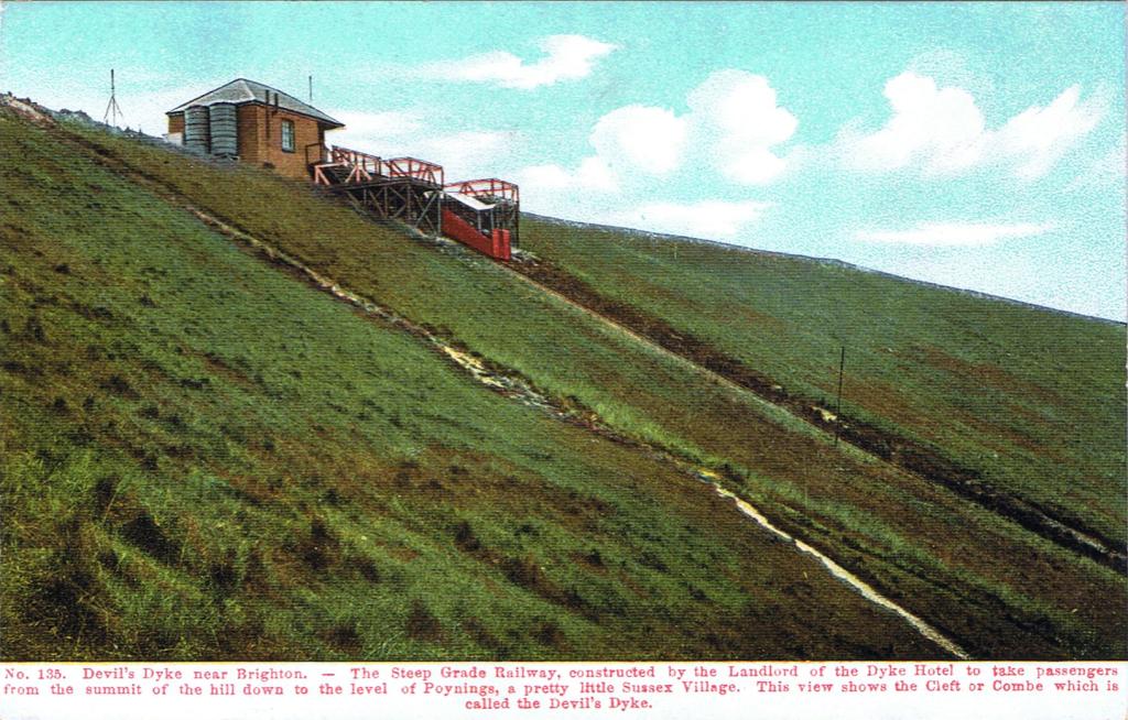
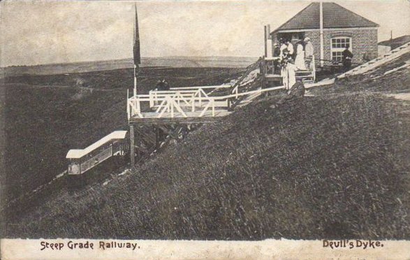
The Steep Grade Railway 1897-1909
James Henry Hubbard, the great Victorian entrepreneur of Dyke entertainment, conceived of linking Poynings to his amusement park with a funicular railway in 1896. It was designed by Charles O. Blaber who was also the engineer for the railway that linked Brighton to the Dyke and it was constructed by a yacht building firm from Southwick. The funicular was built in six months and opened in July 1897. Unlike the aerial cableway that had opened three years earlier, the funicular was not at the leading edge of engineering design. Funicular railways first appeared in the sixteenth century and were in common use throughout the world by the end of the nineteenth century. At least so far as the UK was concerned, 1897 was almost the end of the funicular era. For example, the industrial funicular built at Offham Chalk Pit in East Sussex in 1808 had been shut down in 1870. A company that still builds funiculars today reports that none were constructed between 1902 and 1992. The only unusual feature of the Steep Grade Railway is that it was built inland. Almost all UK passenger funiculars have been built in coastal towns (there are two in Hastings, for example). The best known exception to this seaside generalization is the funicular at Bridgnorth in Shropshire. Like those in Hastings, this little railway remains in use today. But the Bridgnorth funicular links two halves of a town, not a tiny village and an isolated hotel cum funfair. With the benefit of hindsight, the Steep Grade Railway made no economic sense at all.
A funicular railway is one in which a cable is looped round a pulley at the top of a slope and two cars are attached, one at either end. One car ascends as the other descends. In the ideal world of school physics, the two cars exactly balance, cables have no mass, and gravity can be removed from the equation. The only role of the associated engine is to overcome the forces of friction. In the real world, the cars almost never balance (passenger numbers will differ, for example), wire cables are heavy, and changes in the gradient mean that the gravitational pull of the cars depends on where they are on the tracks. So the engine has some serious work to do.

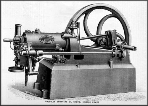
The engine in the case of the Steep Grade Railway was a water cooled 25HP Hornsby Ackroyd oil engine similar to the Crossley engine that powered the aerial cableway. The engine ran continuously and was combined with an elaborate clutch and braking system.
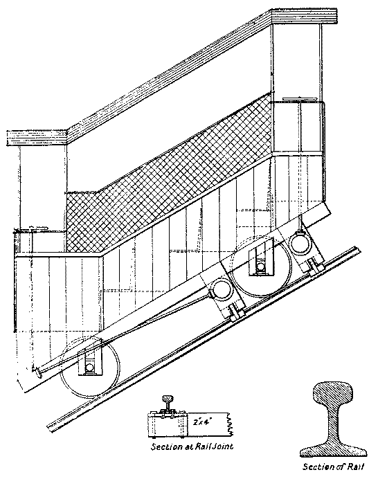
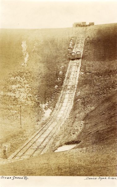
The cars were open and had seats for twelve passengers plus space for a conductor and bicycles. They moved at a sedate 3mph along a 3ft narrow gauge track. The track was 840ft long spread over three different gradients and rose to a height of 395ft. There was a brick platform at the bottom of the track and spring buffers, but no station. A newspaper report published a few days after the opening ceremony tells us that:
The cars do not move rapidly but are kept well under control from first to last. They travel easily, and smoothly, and there is an utter absence of anything in the way of sensation. The journey is certainly a curious one, but that is all. Of course it is pleasant, the cars affording a charming view of the country, and there is the further attraction of the novelty of the whole thing. [Brighton Gazette, 29th July 1897, quoted by Clark 1976, pages 56-58.]
A couple of weeks later, the same newspaper reported (indirectly) that the August bank holiday traffic on the funicular was at the rate of 400-600 passengers per hour. “Good business”, as they put it. But it wasn’t to last.
By 1899 the company that owned and operated the Steep Grade Railway was effectively bankrupt and the railway itself had stopped working. More money was borrowed, the railway was repaired and then, in 1900, it was sold at auction to the original owners for less than 5% of the original building cost. Operations resumed and continued until 1908 or 1909. James Henry Hubbard himself had emigrated to Canada in 1907 after getting into financial difficulties. Although the funicular was used to ship provisions up to the hotel, as well as produce en route to Brighton by rail, it may nonetheless have contributed to Hubbard’s difficulties: the day-trippers from Brighton upon whom he relied for most of his income undoubtedly used it to visit the tearooms in Poynings and Fulking, thus reducing custom at the various eating establishments and other attractions that he ran at the top of the Downs. Meanwhile, a direct bus service to Poynings had been introduced — which surely made the rail route to Brighton over the Dyke seem much less attractive to residents of that village. The Steep Grade Railway was finally dismantled and removed around 1913.
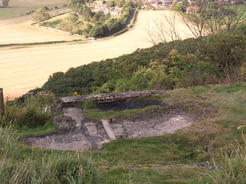
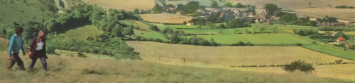
If one stands at the western edge of Poynings on a sunny evening and looks up at the Downs, the route that the funicular track took can still be seen quite clearly, looking much as it did one hundred years ago.
References and further reading:
- Paul Clark (1976) The Railways of Devil’s Dyke, Sheffield: Turntable Publications. Chapter 5, pages 52-62. [Although long out of print, this booklet remains the best source of information about the Steep Grade Railway. It contains plenty of ceremonial, commercial, financial and technical details that are not repeated here.]
- Carole Hampson (2009) Poynings Yesterday. Hove: StewART Publishing Services. Pages 141-142.
- Ernest Ryman (1984) The Devil’s Dyke: A Guide. Brighton: Dyke Publications. Pages 7-9.
- Ernest Ryman (1990) Devil’s Dyke in Old Picture Postcards. Brighton: Dyke Publications. Pages 20-23.
- South Downs National Park Authority (2013) Offham Chalk Pit near Hamsey, East Sussex. SDNPA flyer.
Updated May 2017.
Some other material relevant to the C19 and C20 history of the Dyke:
Walk to Henfield
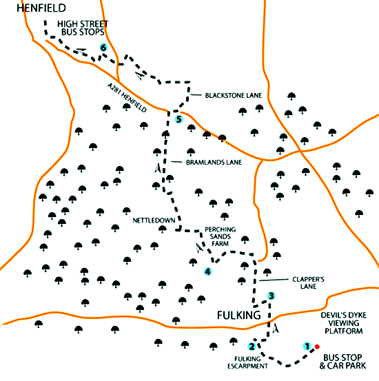 For those who haven’t already done the walk, Eddie Reader provides instructions at The Argus. His map (above) has a certain visual appeal, but you would be better off clutching a copy of OS Explorer 122.
Bank Holiday Walks
The May bank holiday looms and you face the problem of ensuring that your weekend visitors are kept both entertained and exhausted. Walks provide a tried and tested solution to this problem. Over this past winter, the Local Walks page (in the sidebar, under “About Our Village”) has been greatly expanded. There are links to over forty walks as well as a dozen or so walking maps available for download.
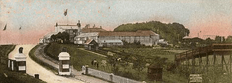
The Aerial Cableway 1894-1909
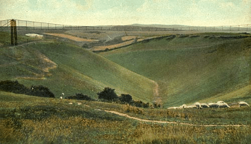
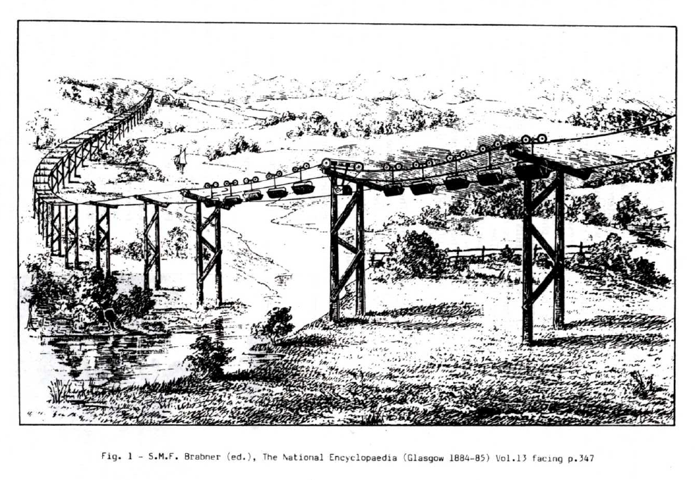
As the illustrations on this page attest, there was once an aerial cableway across the chasm that has become known as the Devil’s Dyke. An early representation of it is a rather primitive sketch that appears in a book by William Axon that was published in 1897, some three years after the cableway opened.
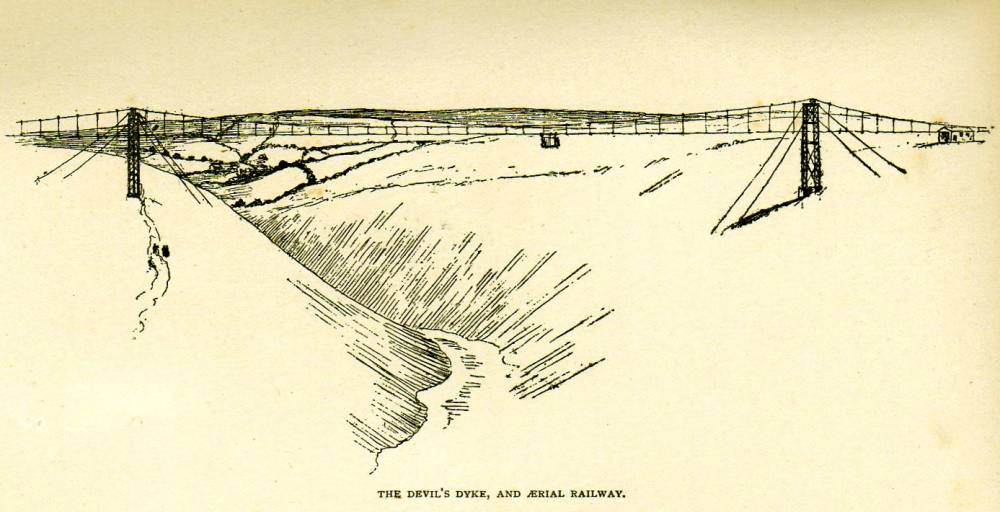
The caption to Axon’s drawing refers to an ‘aerial railway’ rather than an ‘aerial cableway’ which is the term that Clark (1976) uses. Many other terms are used in the literature on such systems: ‘aerial ropeway’, ‘cable car system’, ‘overhead tramway’, ‘passenger ropeway’, ‘suspension railway’, ‘wire rope tramway’, and so on. However, since Clark’s booklet is the best available published source on the Dyke installation, his terminology is adopted here.
The Dyke Railway had begun services in 1887 and James Henry Hubbard, the most energetic Dyke entrepreneur, had bought the hotel and the estate in 1892 and immediately set about exploiting the increase in visitors that the opening of the railway permitted. Thus, on a single public holiday in 1893, he was able to boast of 30,000. The aerial cableway was but one of Hubbard’s ambitious portfolio of attractions designed to boost the visitor numbers yet further. It was first mooted in 1893 and constructed in 1894. It was designed by William Brewer, a civil engineer and inventor.
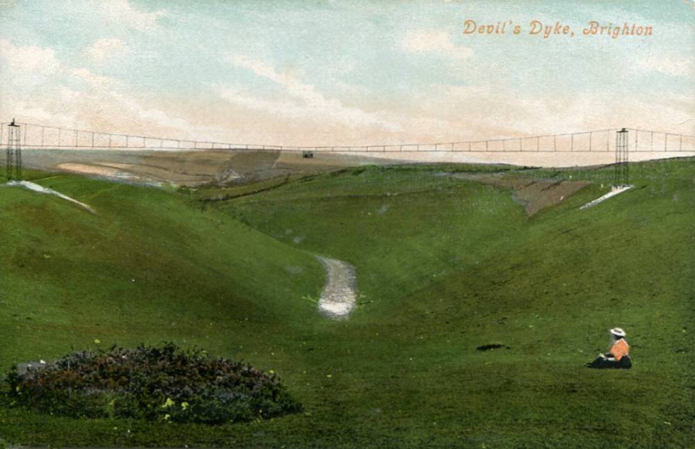
The installation consisted of 12,000ft of cableway stretched across the ravine. The track cables were suspended from a catenary cable by a series of cast metal supports, having two arms extended outwards and joined to the catenary cable by a vertical rod. The track wheels supporting the cars passed over these anchors, and they were adjusted to preclude all possibility of their running off the tracks. One set of wheels controlled the opposite set. The cars were moved by an endless cable worked by a Crossley’s patent oil engine adjacent to the north station and not by electricity as envisaged in the original proposals. [Clark 1976, page 47]
One particularly novel feature was the continuity of the line which passed through supports at stated intervals. In other contemporary systems the line would be confined to two given points, necessitating the unslinging and restarting of the cars. There were two cagework cars in use, each seating four passengers and the time taken to cross from one side to the other was about 2 minutes 15 seconds. There were small stations either side of the ravine approximately 1,100ft apart. The height of the cableway from the base of the chasm was 230ft and the clear span between the two huge iron columns supporting the catenary, and embedded in solid masonry, was 650ft. .. The cable rails were less thick than the catenary cable and even if one of the cables parted the stability of the cars would not have been affected, the support provided by the duplication of cables ensuring the cars being maintained in an upright position. [Clark 1976, pages 47-48]
There are three useful ways to evaluate the cableway: (i) as a magnet for day-trippers to the Dyke; (ii) as a public transport link between Poynings and Brighton; and (iii) as an engineering demonstration. These will be considered in turn.
- Attracting day-trippers to the Dyke?
We can safely assume that this is what mattered most to James Henry Hubbard. But, with the passage of time and the absence of any statistics concerning the popularity of the individual attractions that Hubbard had assembled in his nineteenth century theme park, it is impossible to tell what difference the erection of the cableway made or whether the same investment deployed on other attractions would have done better. Paul Clark is sceptical:Although the aerial cableway had a good start there is evidence that traffic steadily declined in the early years of the new century; indeed Mr. Hubbard suffered financial difficulties and he was eventually to emigrate to Toronto in 1907. Without the promotion of Mr. Hubbard the cableway’s future was uncertain and it eventually ceased to operate around 1909 although there is no evidence to suggest the exact date. [Clark 1976, page 51]
- An important transport link?
Several writers have suggested that the cableway performed a significant transport function. A Poynings resident could take the steep grade railway to the top of the iron age fort, walk a short distance to the cableway, cross the Dyke, alight, walk a slightly longer distance to the Dyke Station, and catch a train for Brighton. And vice versa, of course. It sounds rather plausible. It even looks plausible when you inspect a 2D map of the locale: if you draw a straight line between the steep grade station and the Dyke station then that part of the line that crosses the Dyke exactly coincides with the route of the cableway. However if you look at a contour map, or simply walk the site, then the plausibility evaporates. The Dyke is not the Grand Canyon. You can just walk round the western end and bypass it. You will end up walking about an extra 500 yards but you will have avoided queuing to buy a ticket, waiting for a cableway car to depart, and spending over two minutes in the air in an open cage enjoying the wind along with the views. Assuming a normal walking pace, getting from the steep grade station to the Dyke Station would have taken at least 9.5 minutes if you used the cableway and at most 12.5 minutes if you simply skirted the Dyke and walked the entire distance. The cableway could not be justified on public transport grounds. - A significant engineering demonstration project?
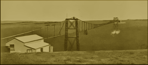
As we have seen, there is no reason to suppose that the aerial cableway proved to be a great success as a theme park ride. Nor did it make any significant contribution to public transport on the Downs. But Brewer was an engineer and his cableway was a highly innovative piece of engineering. To substantiate this, we need to delve into the history of cableways. Aerial ropeways have been in use for industrial and military purposes for hundreds of years and must date back to not long after the invention of rope itself. However, the modern aerial cableway only became possible after the invention of sophisticated steel cables in the latter half of the nineteenth century. Brewer did not invent the modern cableway — such systems were in use for moving ore, coal, and similar materials prior to 1894. One such system, the Telpher Line, came into operation in Glynde in 1885 and was used to move bricks from a clay pit over a marsh to a goods siding at the railway station (Pope 1987). Most industrial cableways of the period used a single cable both to suspend the car and to pull it. Those uses conflict. You want a strong (hence thick and stiff) cable to carry the load but a flexible (hence thin and light) cable to tow the car. A single-cable system normally had to involve a compromise. In the case of the Telpher Line, no compromise was required since it dispensed with the towing cable altogether: cars had their own electric motors for locomotion.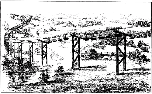
The Telpher Line crossing the marsh at Glynde (Pope 1987) Given the proximity of Glynde, it is perhaps unsurprising that it was the Telpher Cable and Cliff Railway Syndicate Ltd. that acted as the promoter of Brewer’s cableway in 1893. Unlike the Telpher Line, the latter was a two cable system: a relatively thick one was hung like a suspension bridge to act as a rail and a thin one was used to tow the cars*. Another novel feature of the Brewer design was the centrally located rail cable enabled by the holes in the pylons through which the cars passed. Aerial cableways, even to this day, much more commonly have the rail cable to one side or on both sides of the pylons (as at Glynde). And that means that the centre of gravity of the cars is not aligned with that of the pylons. The off-centre load entails using stronger pylons. Side-hung rail cables also make it harder to employ guy ropes on the pylons lest the cars foul them.Clark says that Brewer’s aerial cableway was “the first of its type ever built” (page 47) but it is not really clear what this claim amounts to. Clark may be referring to the characteristics just noted. Or he may be referring to the fact that Brewer’s cableway was designed to carry passengers not freight. One of Hubbard’s promotional posters claimed that his ‘Great Cable Railway’ was the only one in Britain. If true, that would suggest that it was also the first passenger cableway in Britain. Talbot claims that the first passenger cableway in the world was built in Hong Kong by a British firm but fails to provide a date (1914, page 35). Passenger transport imposes different design constraints than freight, most obviously in respect of safety. If a car full of coal becomes detached and drops into a chasm, few beyond the mining site will take any interest in the matter and the economic consequences are slight. A less obvious set of constraints concerns ingress and egress: coal can be dropped into a car from a chute and can leave it through a trap in the bottom. Humans prefer something a little more dignified. Further, cars full of coal or bricks do not get seasick or complain about vibration and noise. Cars full of humans do. From what we know, Brewer’s cableway provided solutions to these various constraints.
The most obvious problem with Brewer’s creation was that it was in the wrong place. It had no real transport function crossing the Dyke. If it had been thrown across the Avon Gorge or the River Severn, say, then it might still be in use today. And William Brewer might have joined at least the second tier in the pantheon of Victorian era engineers.
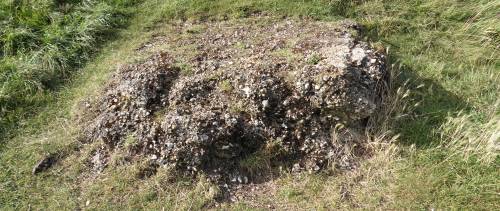
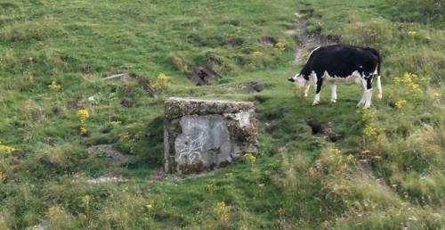
Today, all that is left of William Brewer’s magnificent piece of engineering are two ugly chunks of concrete positioned either side of the Dyke. No visitor unfamiliar with the history would guess that they once supported a graceful iron and steel suspension bridge.
*In reality there were more than two cables involved: the catenary at the top, two for the rails (one in each direction) the cable loop used for towing the cars, and additional cables to brace the pylons.
References and further reading:
- William E.A. Axon (1897) Bygone Sussex. London: William Andrews & Co., facing page 142. [Although this book contains a drawing, it does not appear to contain any discussion of the cableway.]
- Paul Clark (1976) The Railways of Devil’s Dyke, Sheffield: Turntable Publications. Chapter 4, pages 46-51. [This booklet seems to contain the only published account of the history of the cableway. There is a good deal of information in it, over and above that quoted here.]
- The Hallidie Wire Ropeway (1902) Catalogue No. 21, Part 1. San Francisco: California Wire Works, PDF. [This is a well illustrated and informative brochure from a company making aerial cableways for the mining industry. A photograph on page 21 shows a two-person wire cage car.]
- M.I. Pope (1987) Mineral transport by the Telpher system – the pioneering work of Prof. H.C.F. Fleeming-Jenkin (the story of the Glynde aerial railway). Sussex Industrial History 17, pages 13-19.
- Frederick A. Talbot (1914) Railway Wonders of the World. London: Cassell. [Aerial passenger cableways were rare and exotic in 1894. But, as pages 35-44 illustrate, they were rather more common two decades later.]GJMG
Some other material relevant to the C19 and C20 history of the Dyke:
Local Interest Films
Devil’s Dyke – A Victorian Pastime and The Devil’s Dyke in October (Television South 1986). Poynings Village Hall, 8:00pm Friday 5th April/2:00pm Saturday 6th April, admission free.
Mike Airey
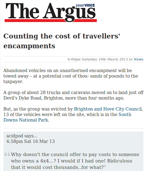
Counting the cost
South Downs Way Walk 7-15 June

An organised nine day walk along the full 100 miles. The Footprints Red Shirts walk with you. Luxury coach transport provided. By far the simplest way of completing the walk. Each day averages around 11 miles. The sectors are as follows: Eastbourne — Alfriston — Newmarket Inn — Devils Dyke — Washington — Whiteways — Cocking — Queen Elizabeth Park — Exton — Winchester. More here.
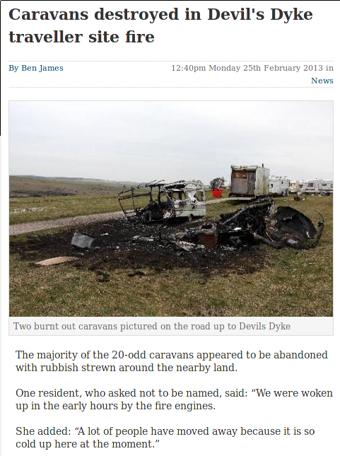
Caravans destroyed by fire
Today’s Argus reports:
Illegal encampments can be reported to West Sussex County Council by contacting Esther Quarm on 033 022 23736 or email esther.quarm@westsussex.gov.uk